
Seidel-UMS ST 7-250B - Remodeling
The history
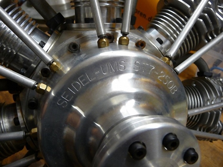
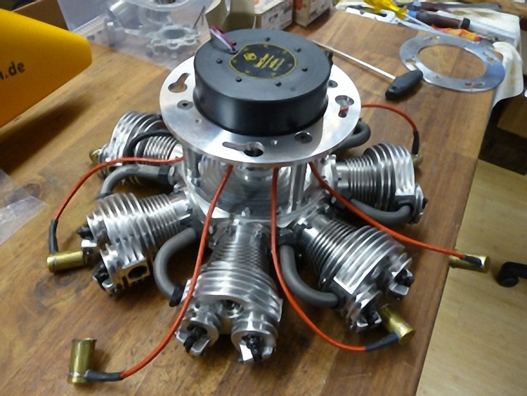
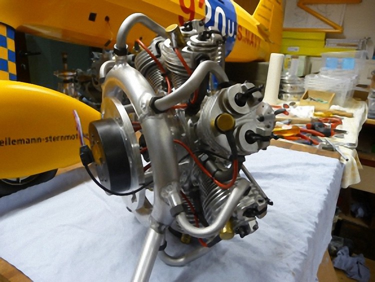
At our second radial engine meeting Klaus Uhl (radial engine fanatic) showed me his latest achievement, a Seidel-UMS ST 7-250B, bought at Seidel Triebwerke in Malsch near Karlsruhe. An engine of the second series with countersunk cylinder heads.
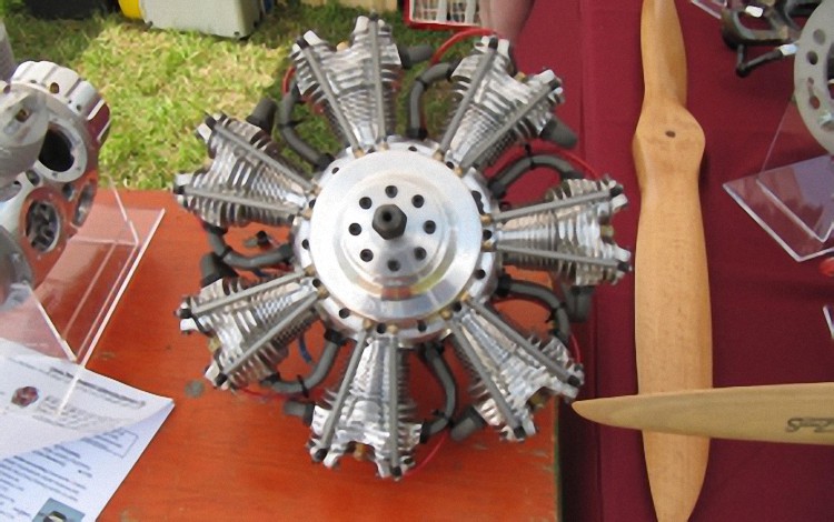
After a few months, Klaus called and told me, he had gotten a call from Wolfgang Seidel telling him the valves in this series of UMS ST 7-250B broke easily, the needle bearings were defective, and that the push rods were made of too soft aluminum and would therefore need to be replaced. He could not take care of the repair work even though the warranty time wasn’t over yet. He could guarantee the supply of parts though.
Klaus asked me to do the repair as well as further modification. I gladly agreed. He is after all a faithful participant and helper at our radial engine meetings.
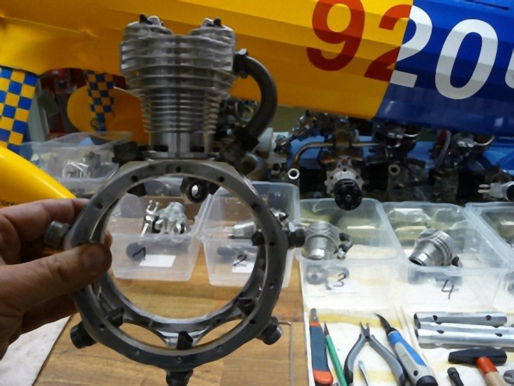
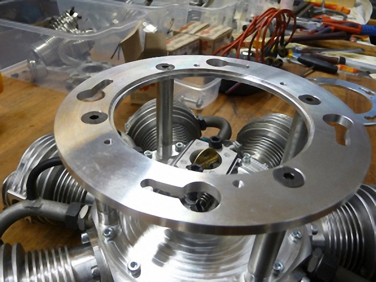
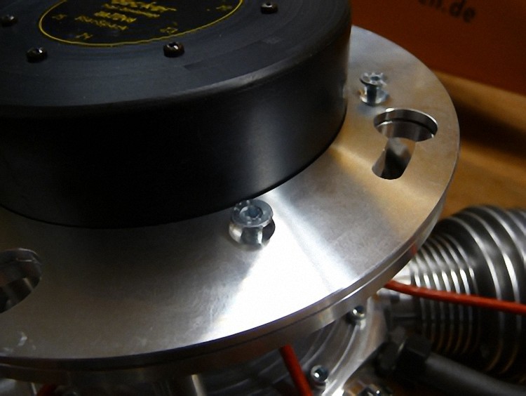
First I reconstructed the engine support plate. The holes for the screw connection to the engine frame remained untouched. I decided to make a two-parted plate so the ignition has a secure fit.
The ignition was originally fastened with only three screws. After checking closer I also found out that the original plate was crooked and bent.
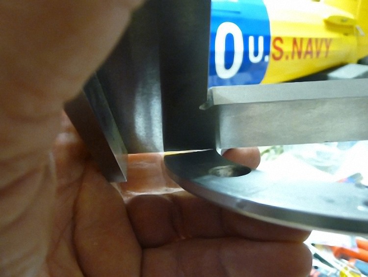
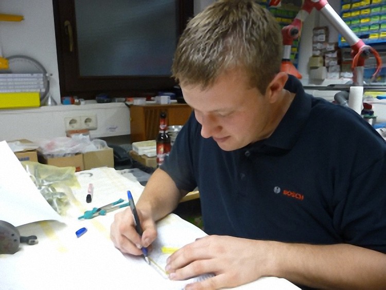
Plate is measured ...
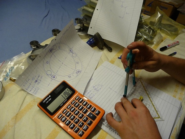
... and drawn
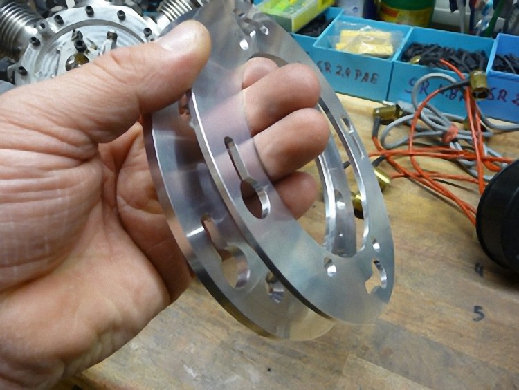
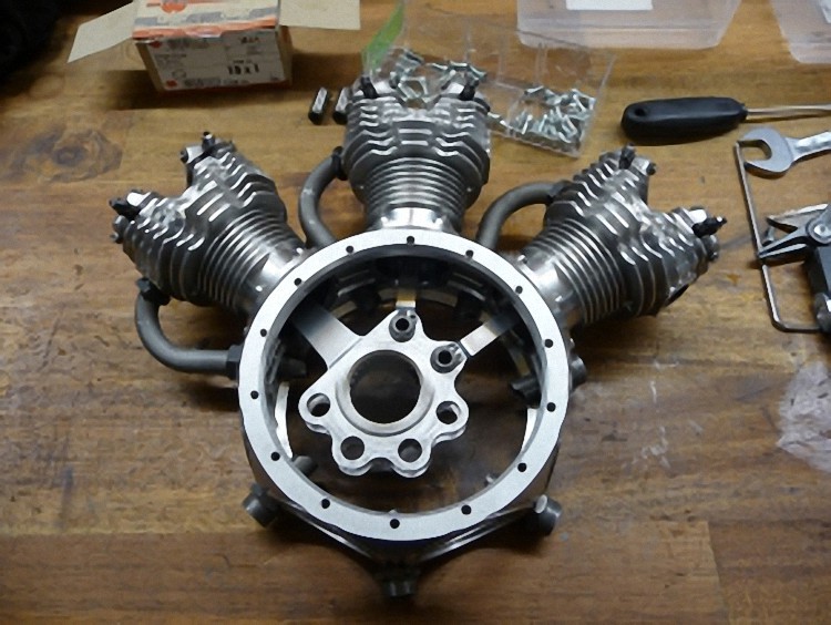
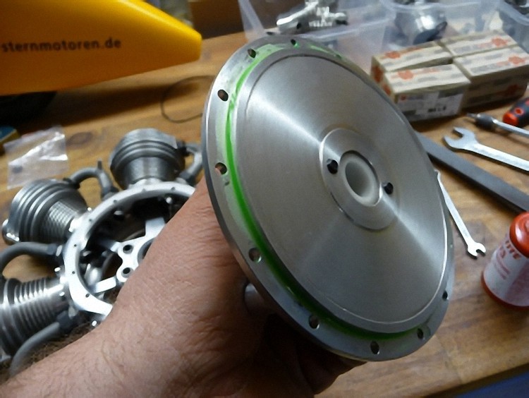
Newly made engine support plate ...
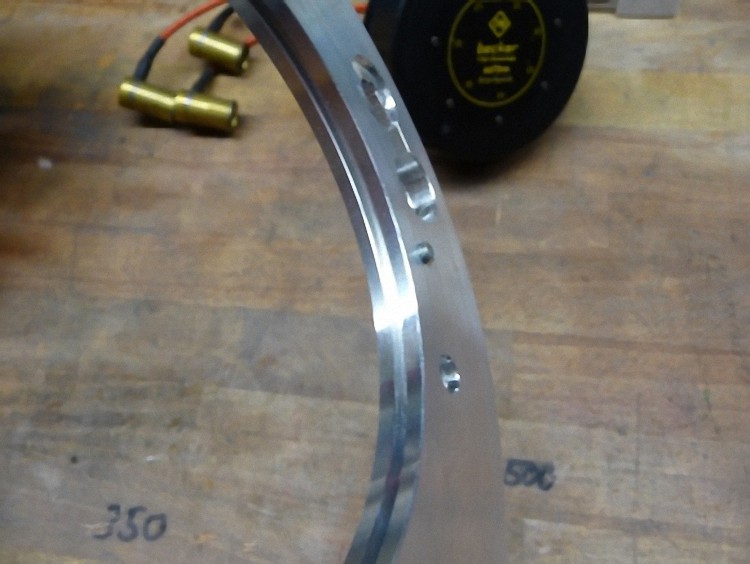
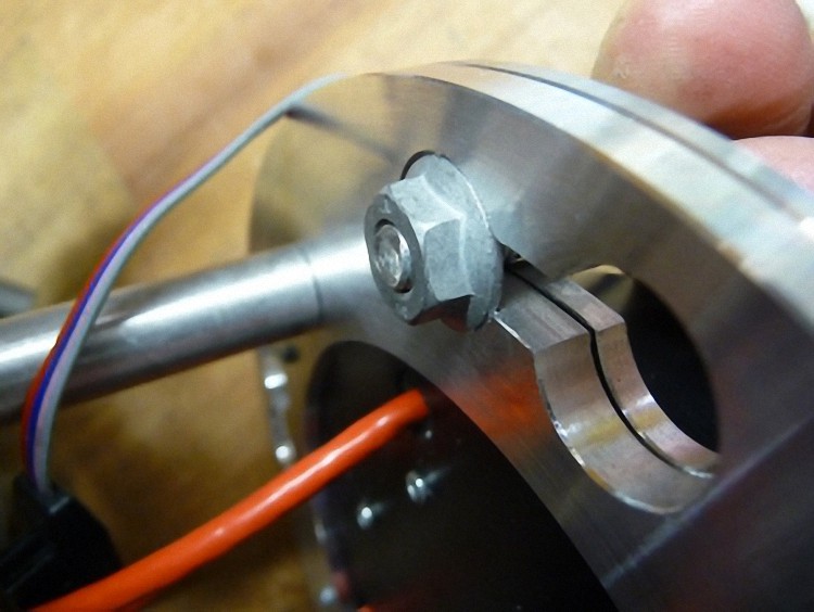
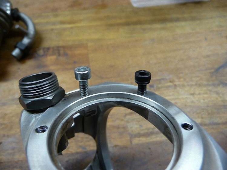
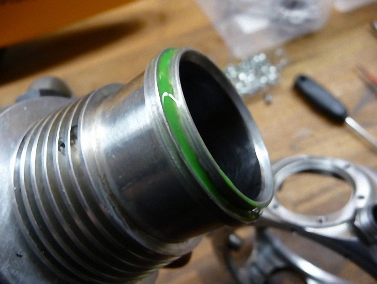
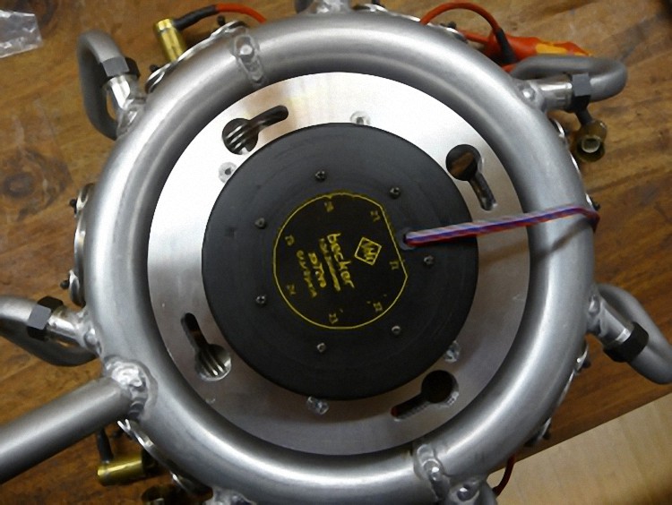
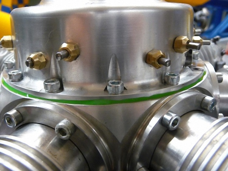
The ignition sits in the ring groove.
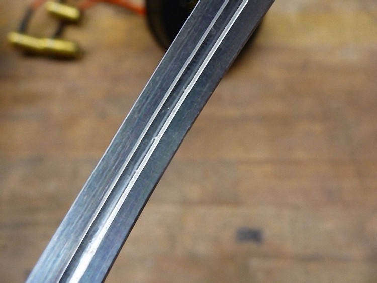
Ring groove for ignition
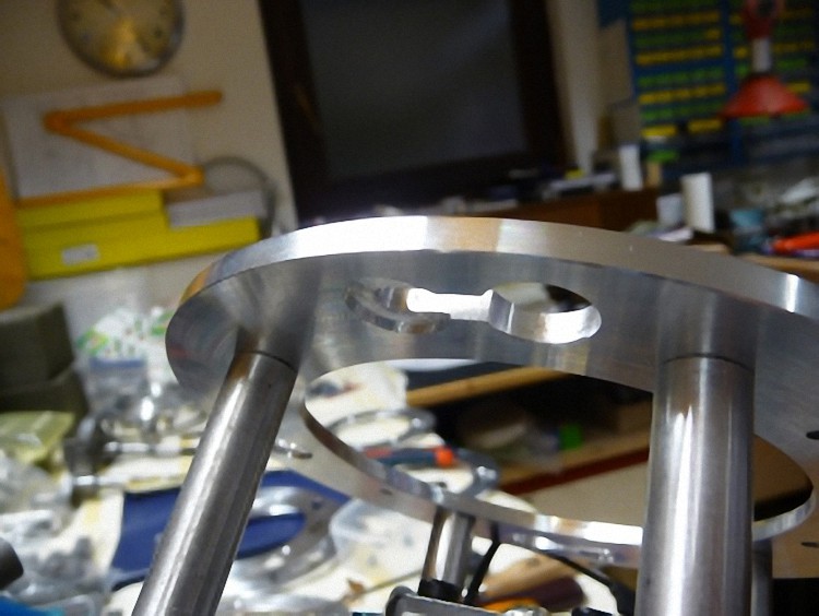
Bayonet catch
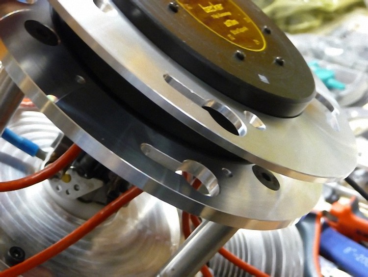
Now the ignition system is mounted as a test and the bayonet catch is put to the endurance test. It worked straightaway and fit exactly into the countersunk part.
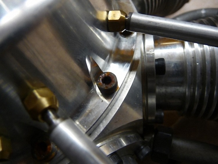
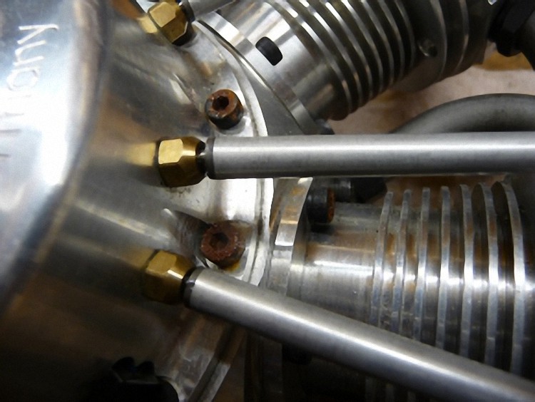
The rusted cam case screws bothered me right from the beginning. Unfortunately the rusty parts had already eaten deep into the aluminum and had to be downright polished out.
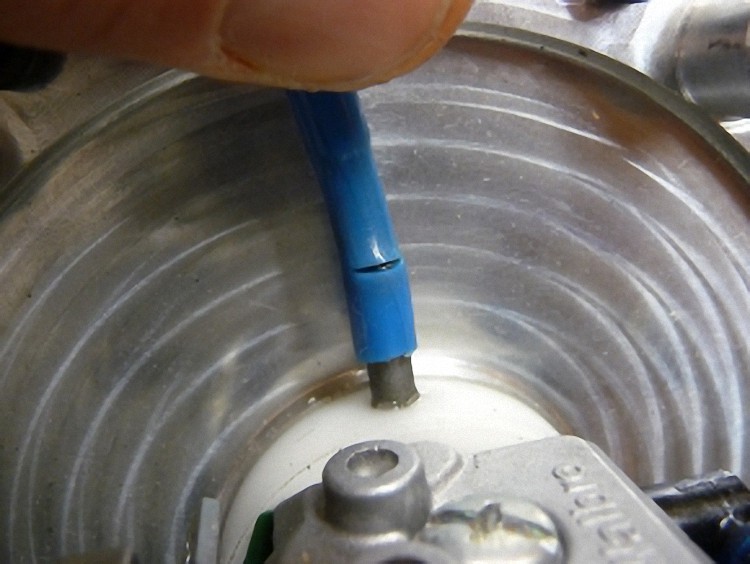
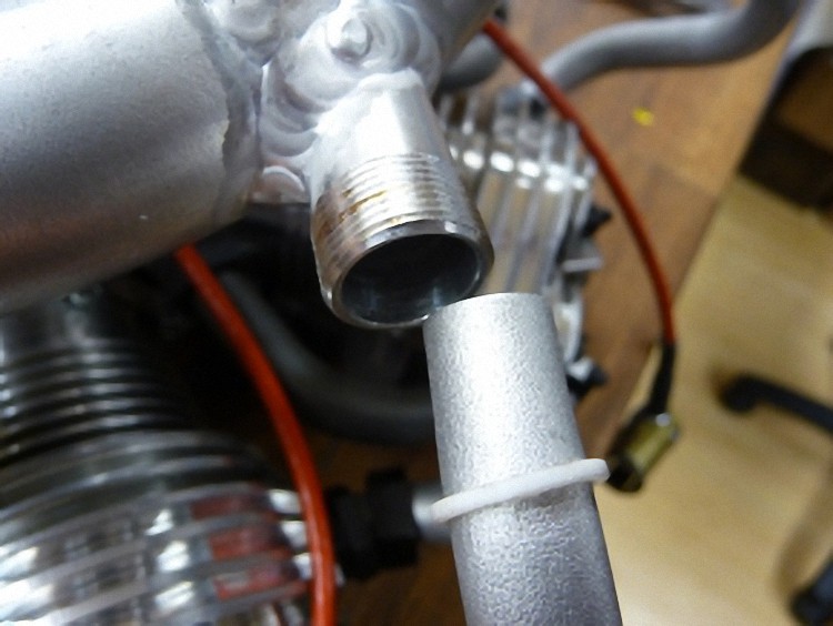
On further inspection I noticed that the tubes to the carburetor, that give the impulse to the membrane, was slightly ripped. So the engine could only run difficultly, if at all.

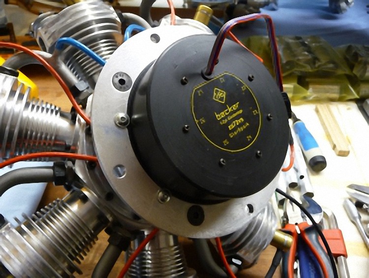
Before taking apart the engine I had measured the ignition, how the sensor is oriented to the dead ignition stroke. For that I had asked Company Becker to make me an electronic little helper.
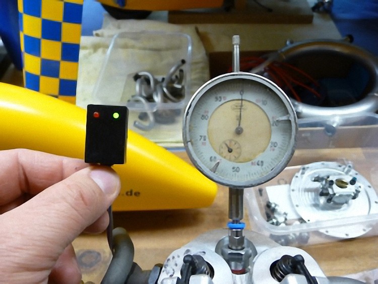
So the ignition was adjusted to 15° prior OT. Usually it should be 0° at OT so the engine doesn’t kick back while starting. The ignition then adjusts every 1000 rpm to about 3,9° advanced ignition (i.e. at 5.000 rpm = about 19,5°).
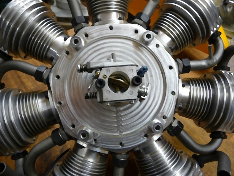
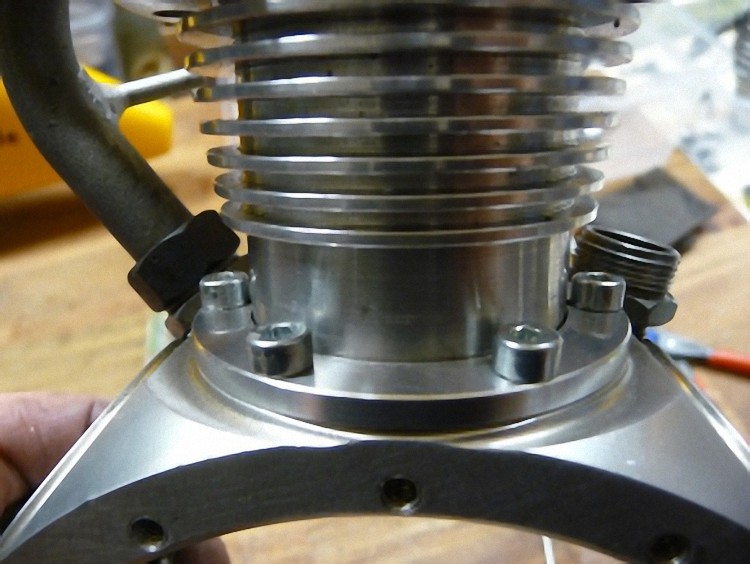
Dismantling rear plate with carburetor and mounting engine carrier
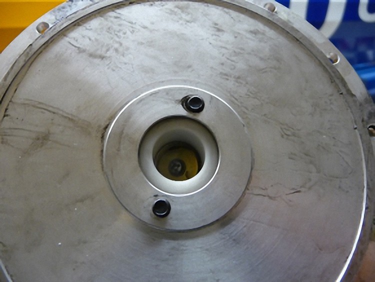
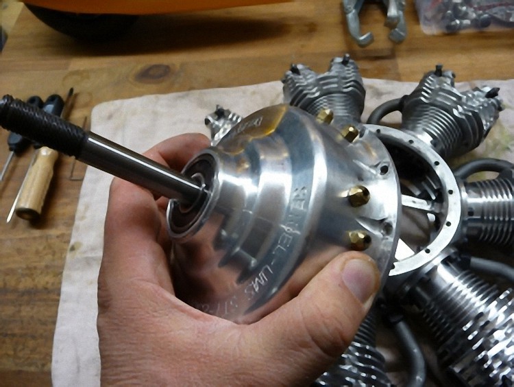
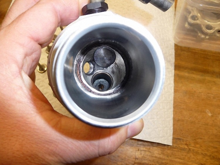
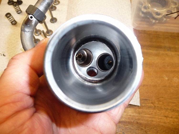
At the front the cam case is unscrewed.
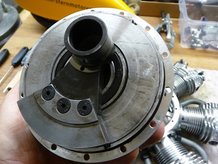
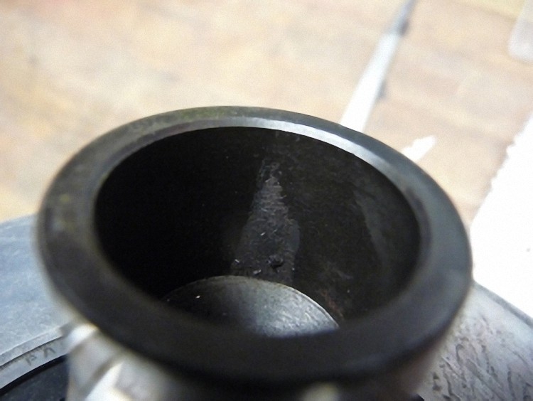
While looking into the crankpins I had to find that metal shavings from production were still there. I carefully removed them.
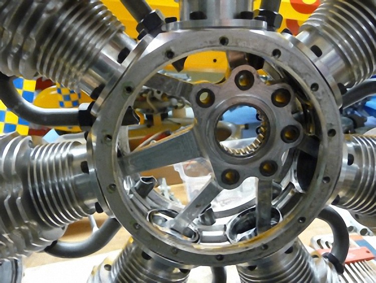
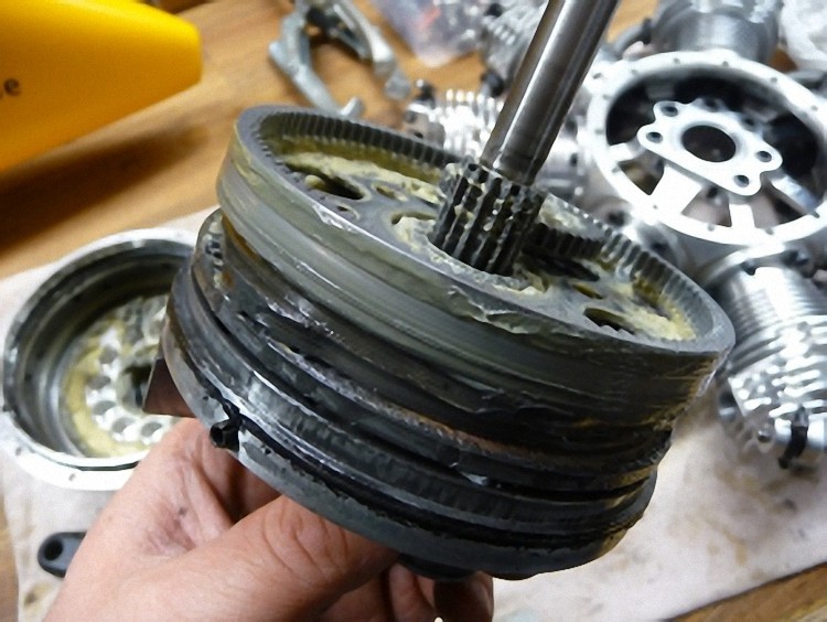
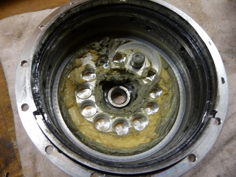
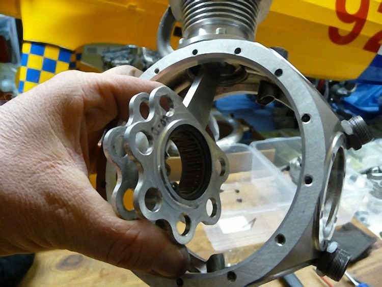
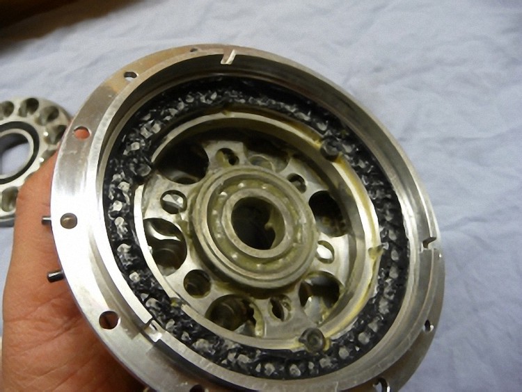
Pressed out crankshaft with cam disc, and ignition magnets. It is astounding how little grease was in the case. Even though the engine was new and had only run at the factory. Luckily the grease had not made it to the weight-reducing holes on the lid.
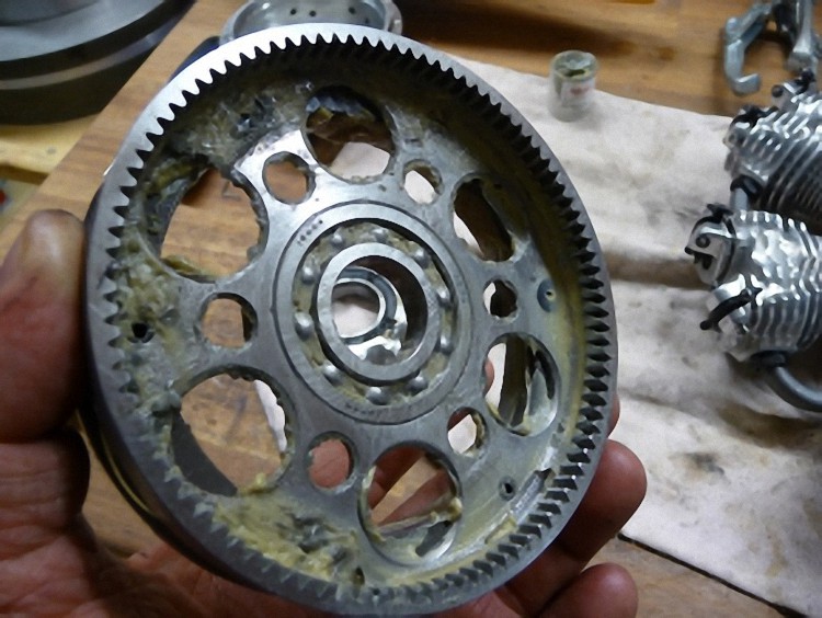
Good to see here: The aluminum disc that takes up the magnets. 21+3 negatively polarized to recognize the first cylinder. As the cam has three cam pairs and is underpinned 1:6.
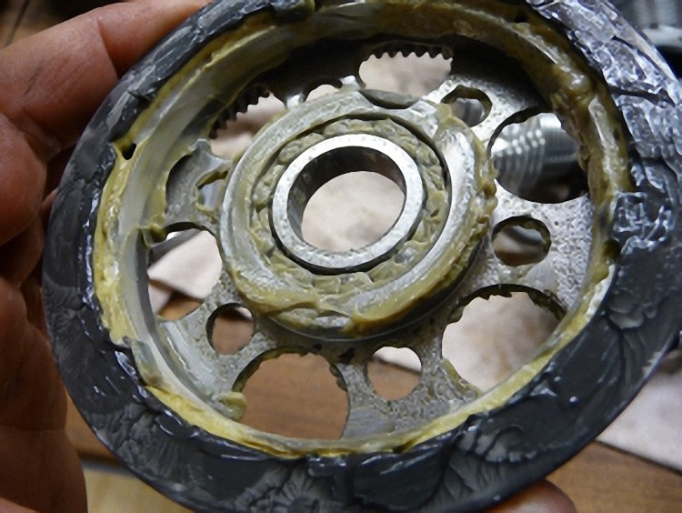

The cam disc seems to be in good shape. All teeth are luckily there :-)
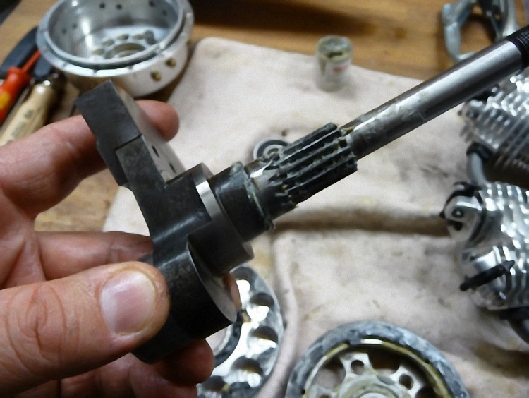
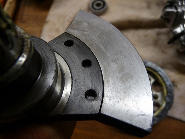
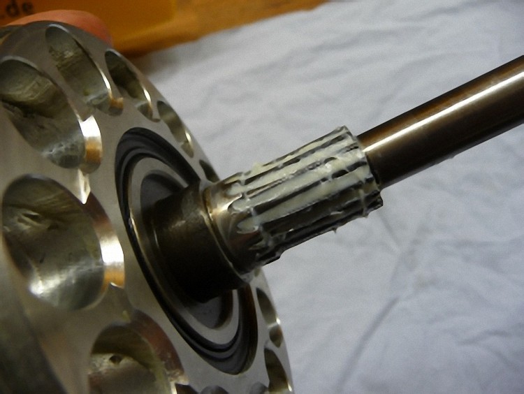
The crankshaft gearing also looks good. The crank arm is screwed to the crankshaft. The only thing surprising is that the Indian doesn’t use the whole thread depth.
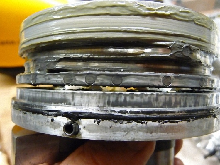
All connecting rod bolts are pulled and the individual cylinders are dismantled. Sadly only one piston ring is built in. For a good and lasting compression two seal rings are actually needed.
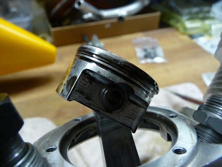
At the factory the connecting rod bolt was pressed in at an angle. I had to adjust it.
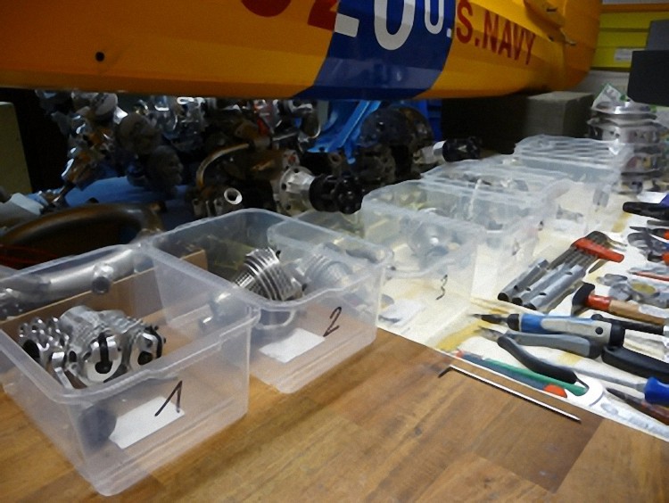
All parts are taken apart and neatly stored away. It is very important to make sure all parts remain paired up.
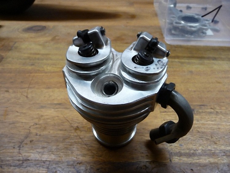
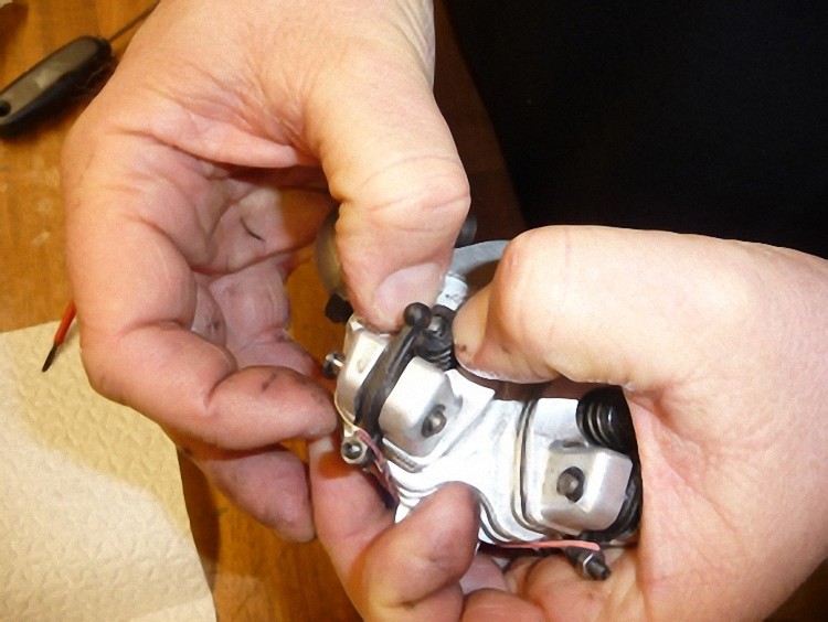
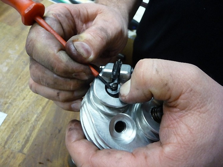
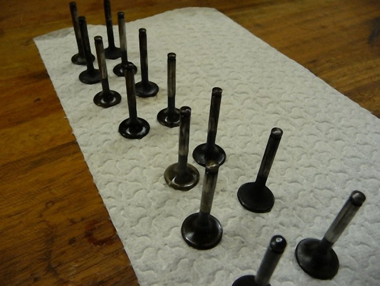
The valves are now disassembled from the cylinder head.
It is not so easy to disassemble the little wedges without losing one. If you don’t pay attention for a second, the wedges fly all around the workshop.
All parts are cleaned and now ready for assembly.
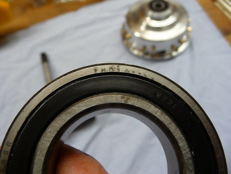
Now it is time to check the cylinder heads’ tightness. As the old parts (valves) go into the trash, we make a breakage test.
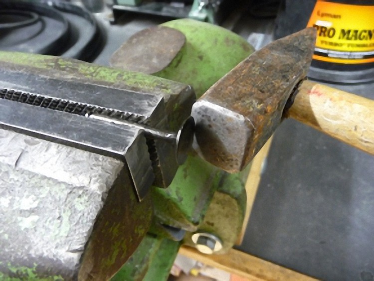
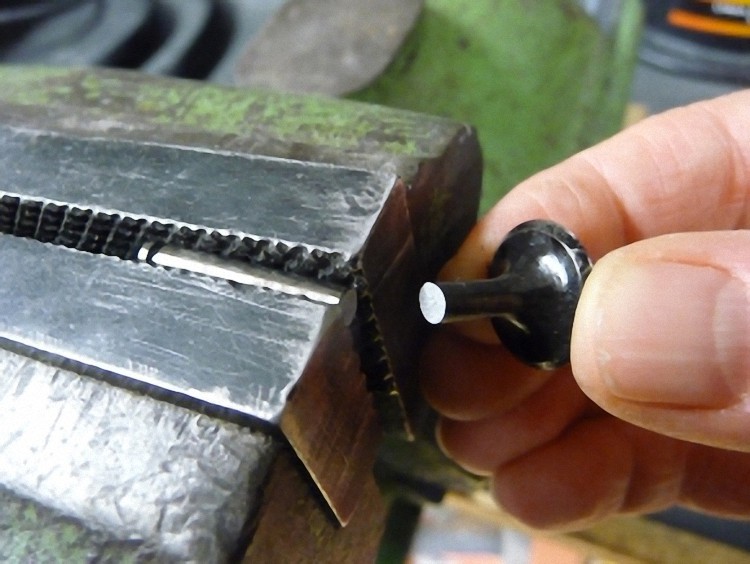
A shocking result. The old valves break like glass even though I had only tapped them lightly with a hammer.
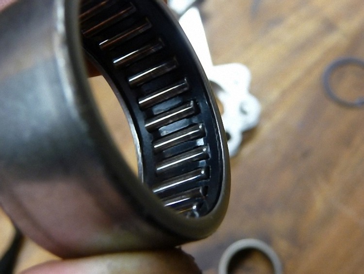
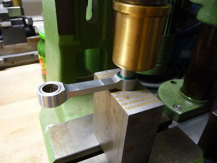
I exchanged the Indian needle bearings of the main connecting rod for German INA needle bearings with wide needles. For this building size that is essential for the tilting moment on the crank pin.
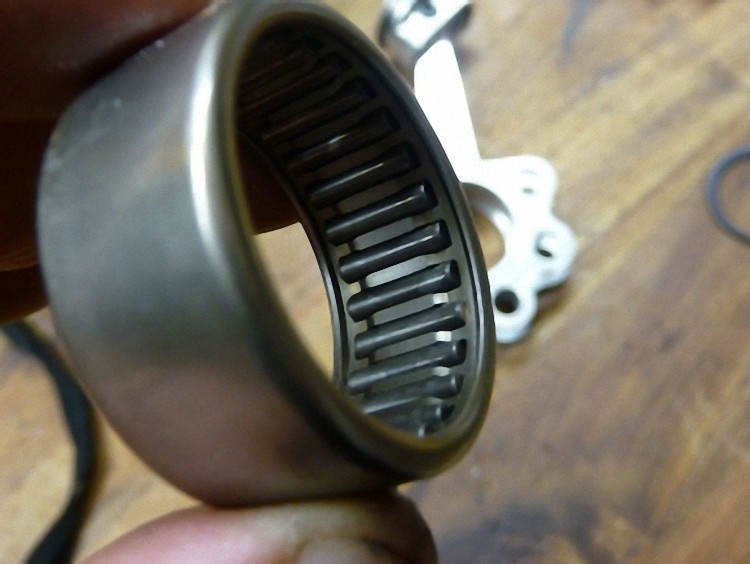
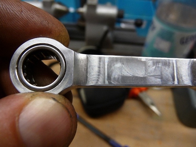
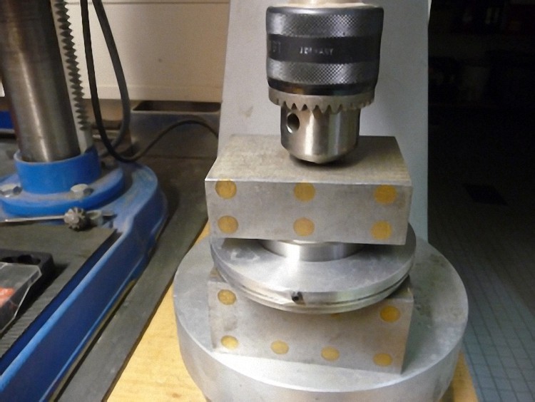
The new needle bearing is now pressed in. The result looks very good. Next we check if the bearing clearance of the new bearing has changed on the crankshaft’s crank pin.
Everything fits. The tolerances are unchanged. I also swapped the little needle bearing in the connecting rod head. According to Wolfgang Seidel the needle cages break open here and the needles fly around the engine total --> wreckage :-(
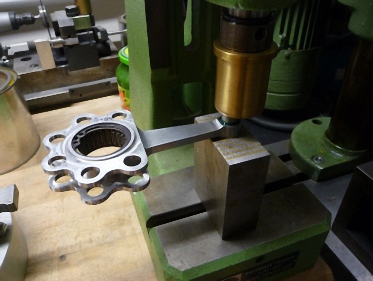
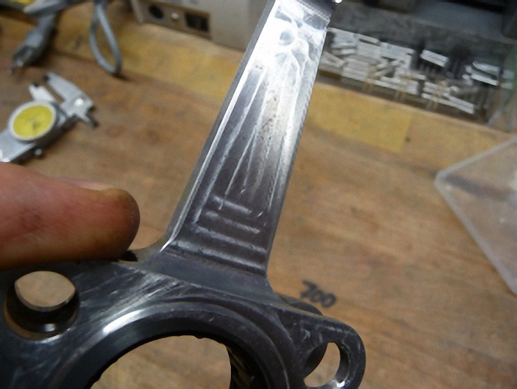
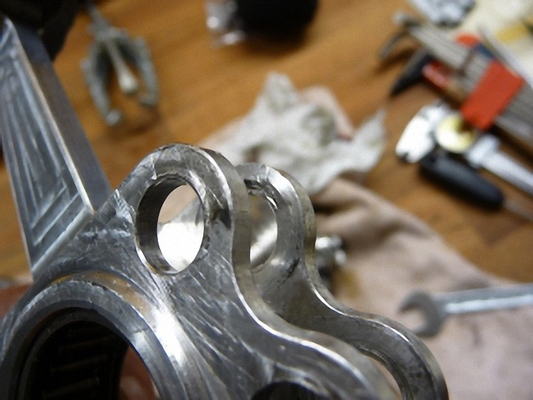
What I personally dislike completely are milled lanes on the main connecting rod. It is a highly strained building component, that mustn’t have any notch effect from machining. So, we had to rework and polish completely.
I didn’t bother as much with the other connecting rods and pushed the needle bearings out. I threw them all away and exchanged them with new connecting rods.
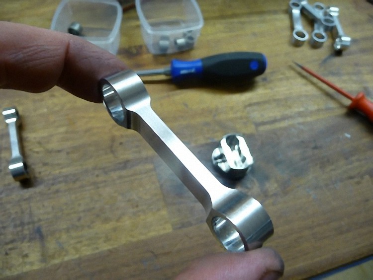
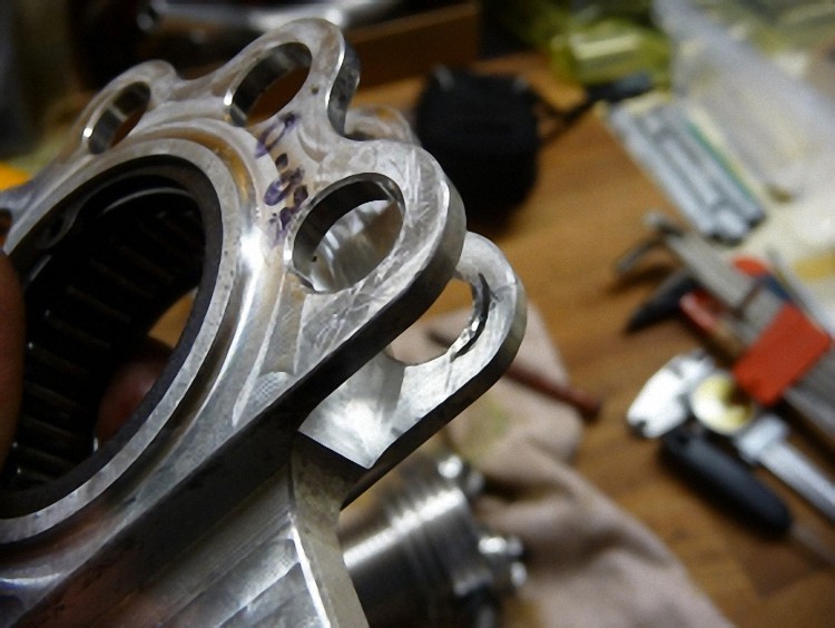
The transition from connecting rod to connecting rod eye was completely gnawed away (as if finished mechanically with a file) and the aluminum itself was soft as butter. That does not mean that it’s not working; however it doesn’t meet my technical understanding to remount these again.
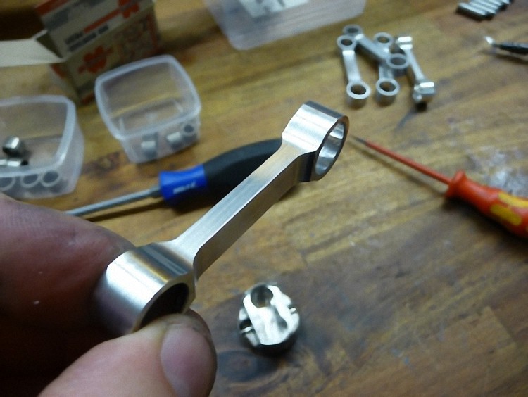
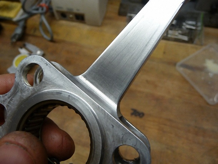
This is what a new and freshly polished connecting rod looks like. I also glued and pressed German INA needle bearings into this one.
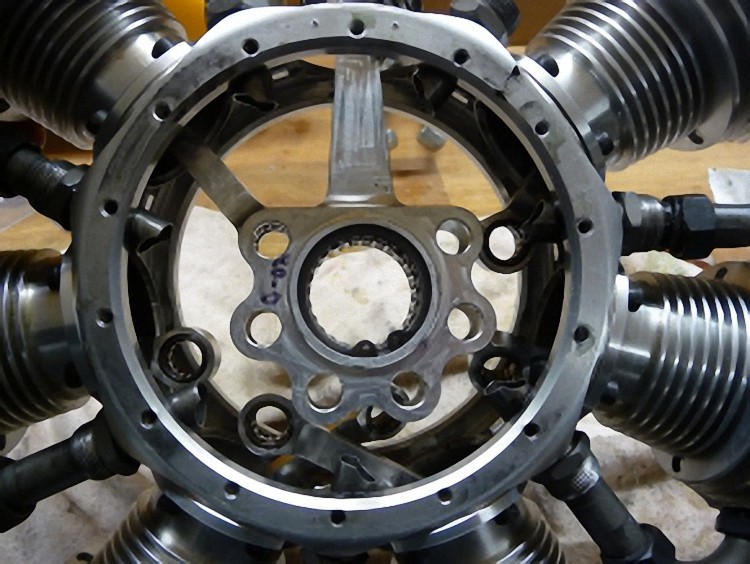
The thread for the cylinder barrel screws in the engine case wasn’t cut deep enough. So I made the drillings deeper and recut the thread. The cylinder was sealed anew to the engine case with surface sealing agent.
The rule of thumb is: The depth of the screw drilling hole should always be twice the diameter of the screw (for M4 = at least 8 mm deep). Also, the right cylinder sealing is very important. The tighter the engine is, the easier it starts up and keeps a low and safe stationary throttle.
I only use screws with a strength of 8.8 and galvanized surface. The assembly quickly proceeds.
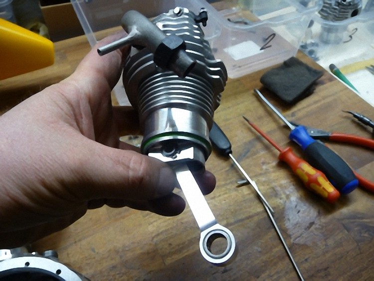
The pistons with the connecting rods are now pushed into the cylinder and the individual cylinders are screwed together one after the other.
The connecting rods now have to be hung and secured into the main connecting rod with a connecting rod bolt.
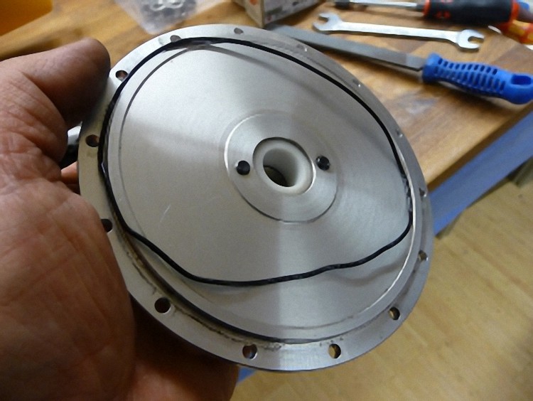
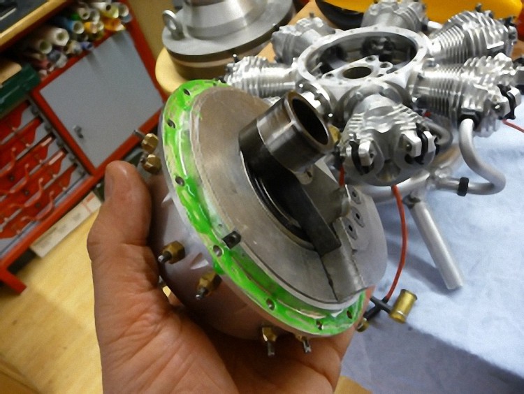
I threw out the original rear plate’s o-ring and exchanged it with surface sealing agent. O-rings settle after a while and become brittle = no sealing. Engine pulls false air.
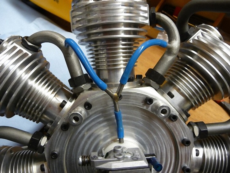
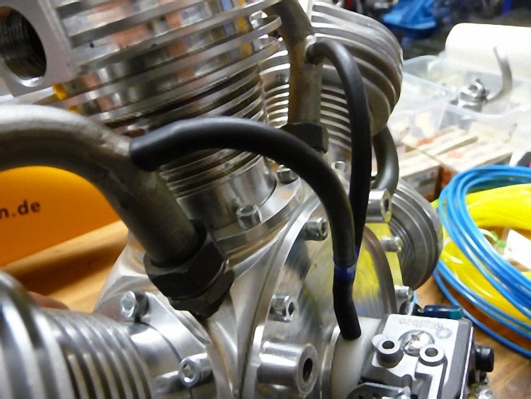
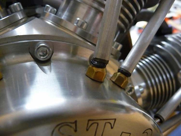
New tubes for the carburetor impulse are pulled in with a new Y-piece as distributor. The tubes are gas resistant and don’t harden, in comparison to the originals.
Mounting the engine carrier
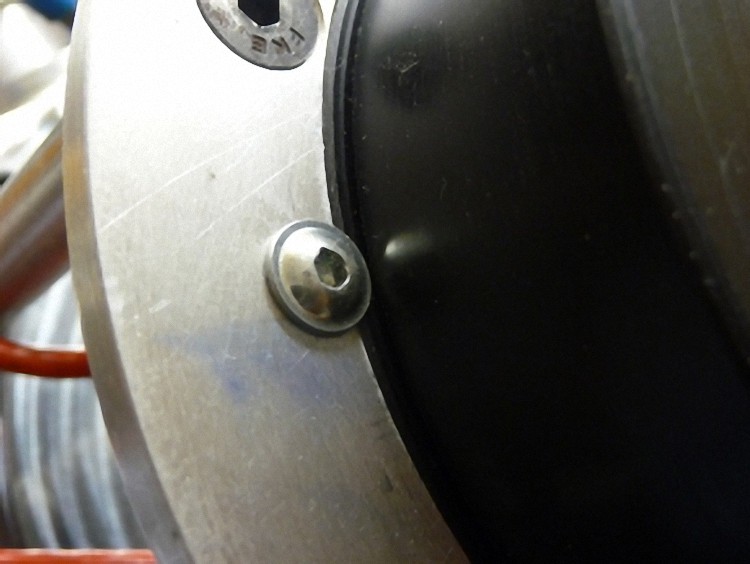
The Becker ignition is fixated neatly into the engine carrier with an adapter plate.

The ring muffler wasn’t mounted ex works but only enclosed. For good reason: It doesn’t fit at all! Over the years I have assembled quite a few RSD and experienced a lot, but I have never seen anything bent so carelessly.
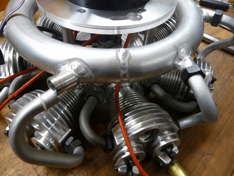
As the ring muffler has to be mounted more or less stressless and in the middle of the engine carrier plate, I rebend all the aluminum manifolds in meticulous rework. I also adjusted the welding sockets with heat treatment.
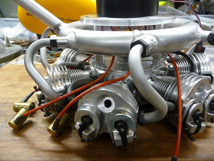
After endless swearing and hours later the muffler is finally where it should be and looking very good.
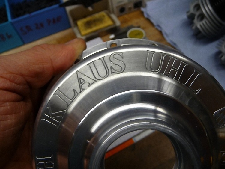
And now to the cam case. It was unscrewed to remove the name and logo of the Seidel Company as well as hammer blows and scratches (new engine?)
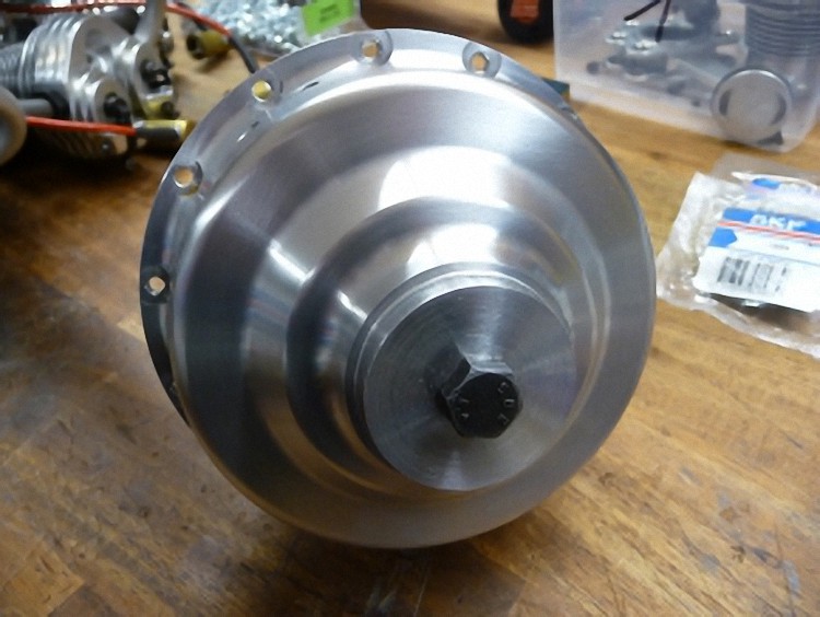
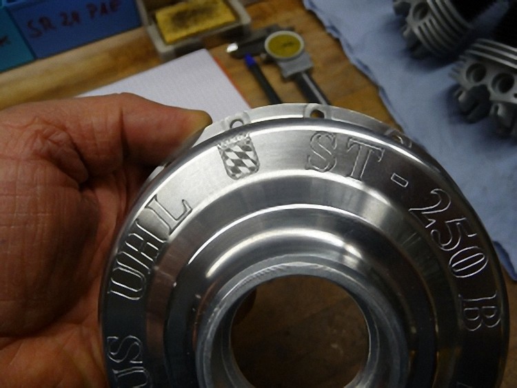
On request of Klaus Uhl his name, the Bavarian seal and the engine details were engraved by our engraver in meticulous handwork and polished by me.

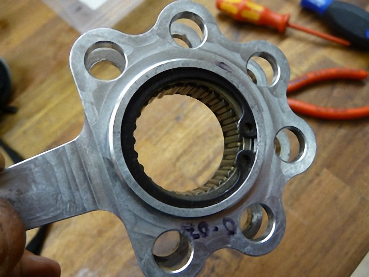
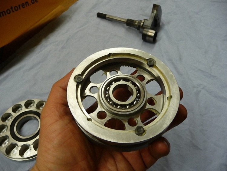
The Indian bearings were quickly exchanged for European bearings.
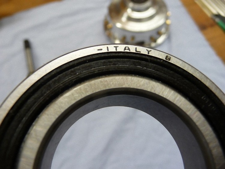
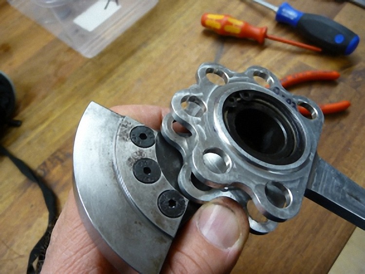
The same also for the main bearing disc that takes on the crankshaft.
And the same for the cam disc. I also glued in the bearing as it is not fastened at all (with a band or safety ring).
The cam is built into the cam case with enough fat filled in to last for a year.

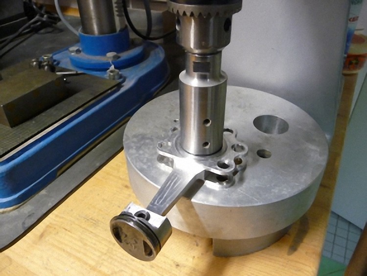
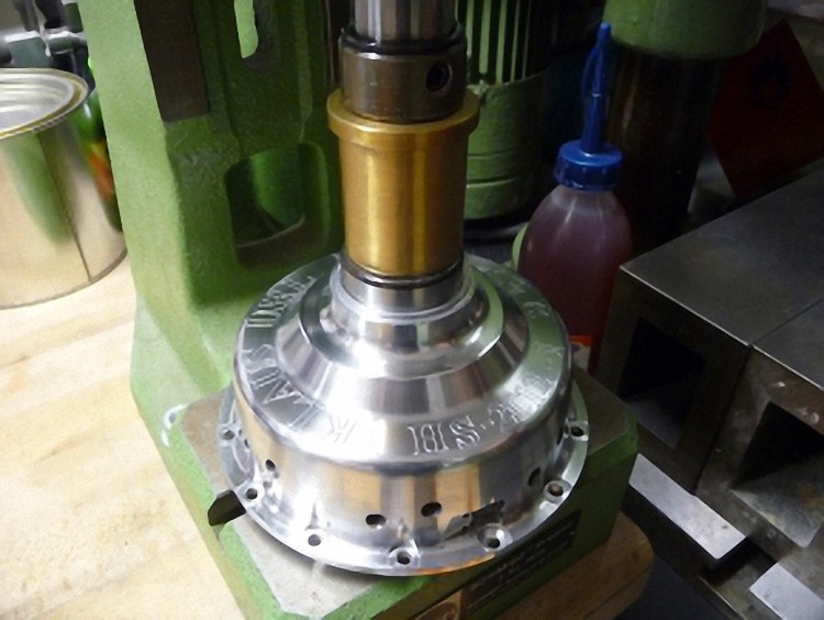
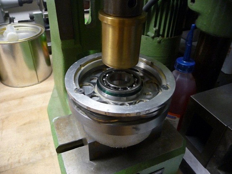
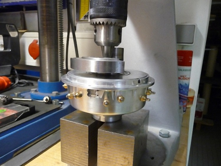
I also greased the crank shaft gearing with fat and, after adjusting the steering times, pressed it into the cam case with a degree wheel (360°) and ignition box (for checking purposes).
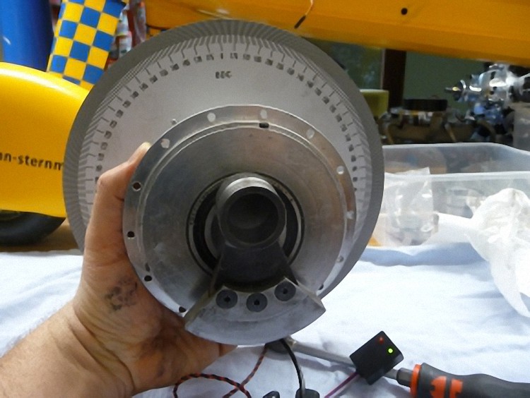
Checking with the degree wheel and pressing in the crankshaft.
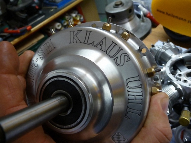
So the engraving on the cam case can be seen even better, I filled it in with black and repolished it.
The cam case is now screwed together with the engine case and the engine is almost finished.
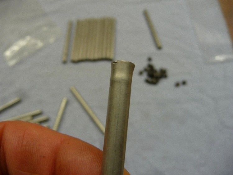
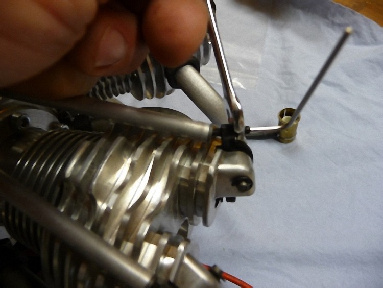
In the original push rods an obvious compression can be seen. That is why I pressed out the inserted parts ...
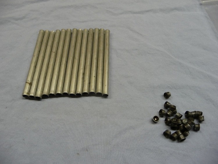
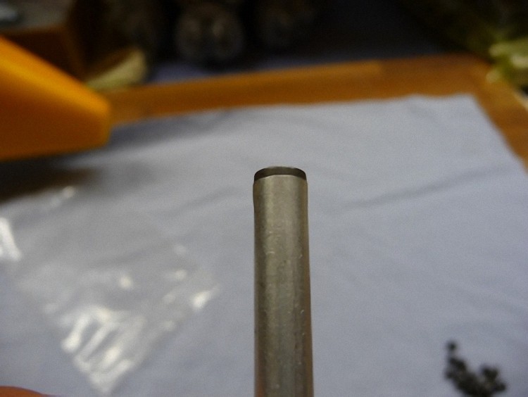
... and inserted them into the new pipes. After that greased well and assembled.
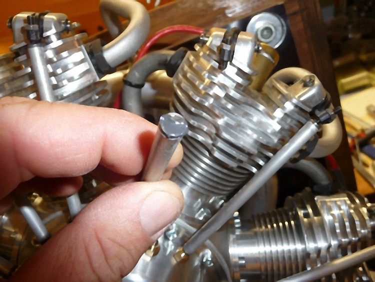
Now the valves are adjusted, i.e. figuring out the slight out-of-round of the cam, in this case 0,15mm and adjusting the valves to 0,1mm.

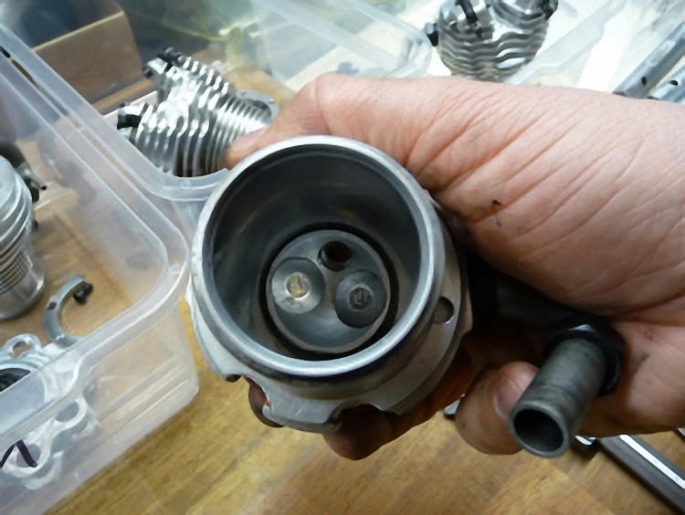
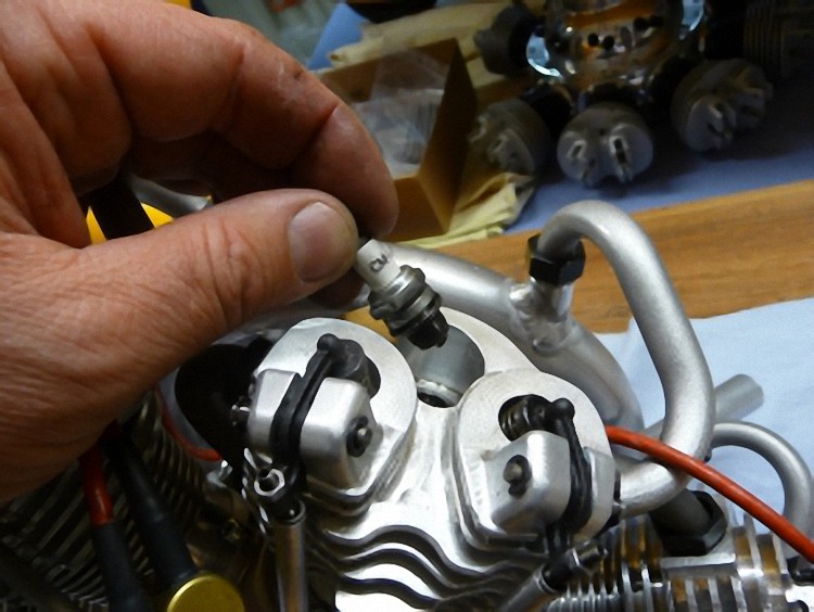
I checked the glow plugs for a clearance of 0,4mm and rebent some of them.
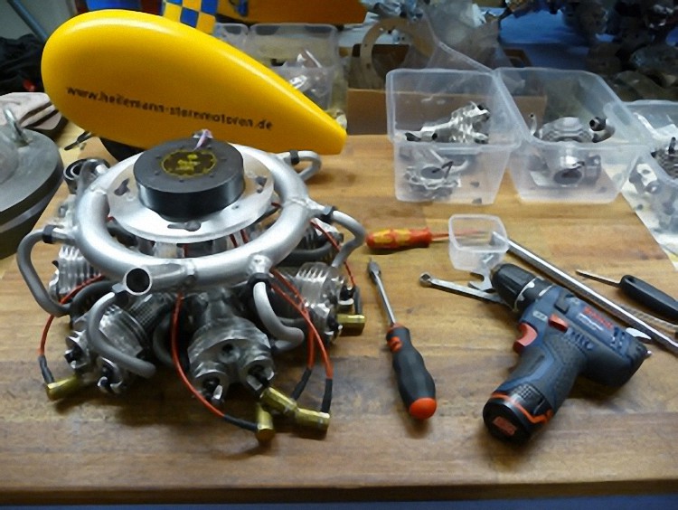
Laying the ignition cable neatly and assembling it for the test bench.
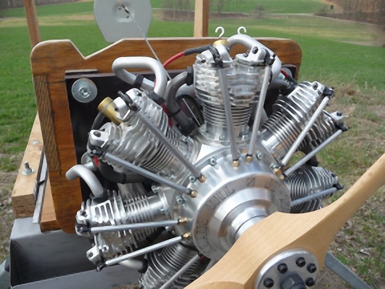
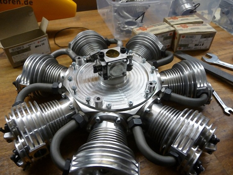
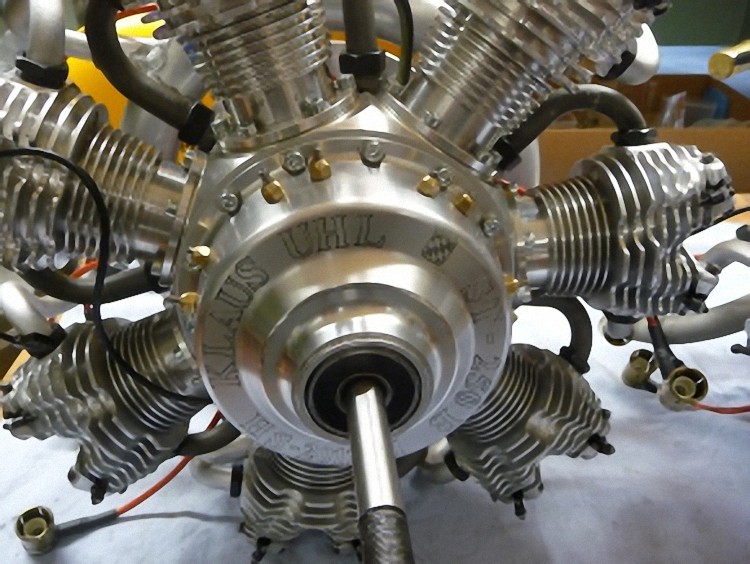
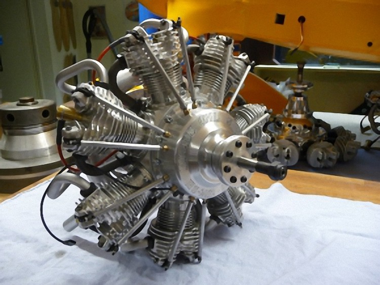
IT IS DONE
The engine starts up very well, runs smooth and has a low and stable stationary throttle.
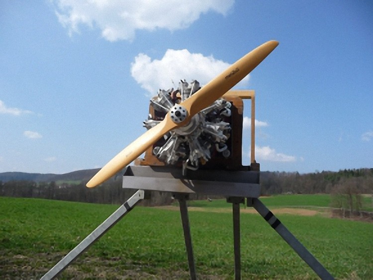

Now Klaus Uhl can receive his engine again after four months of remodeling.
We are already looking forward to seeing the engine fly in his GeeBee, hopefully at the next radial engine meeting.
As always special thanks go to the helping hands in the background: Peter Haag, Florian Karpf, Carmen Kugler and my wife Elke.
Without you it would not be possible to realize such projects.